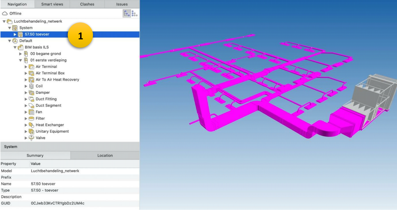
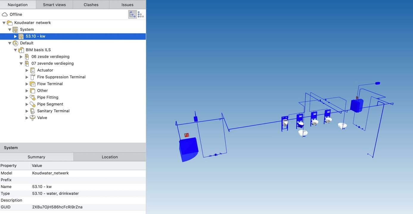
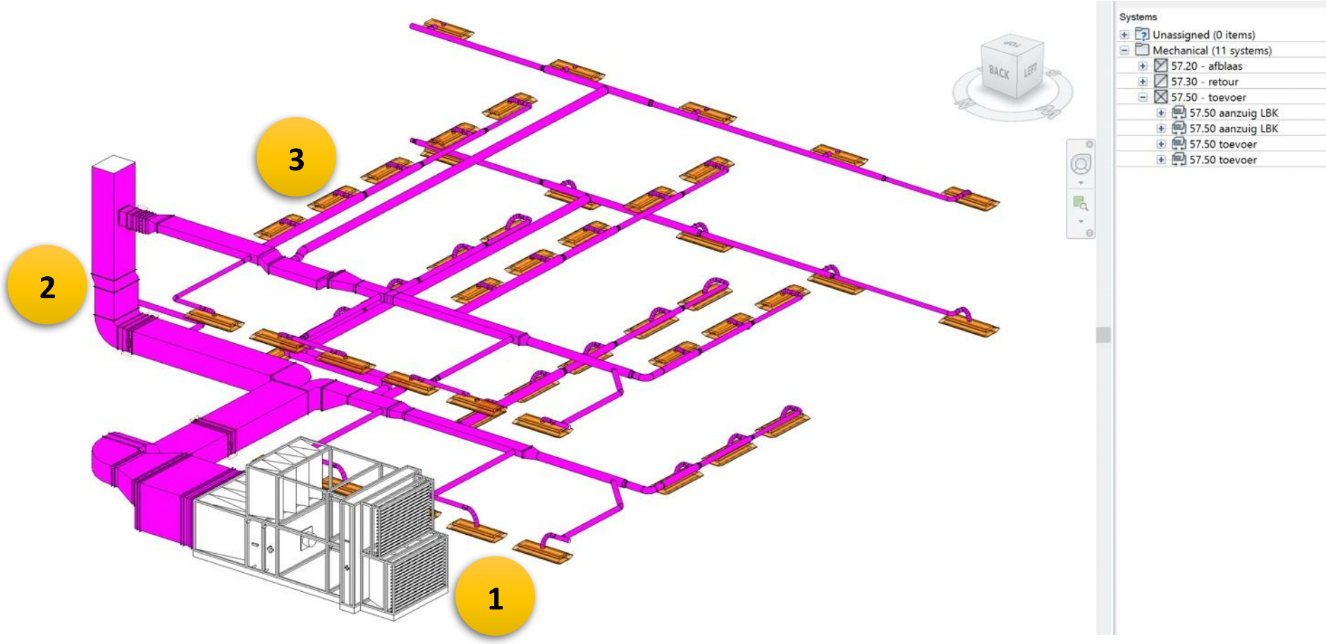
This agreement is intended to clarify the mutual relationship between building services objects within the BIM, based on technical installation systems (which in IFC is covered by IfcSystem). A system is an organised combination of related installation components, which together provide a service for a common purpose or function. A system is thus a functionally related collection of products. The IfcSystem is a relationship definition or grouping relationship. Different types of components are grouped with each other using an IfcSystem. For example source+distribution+delivery point are grouped together with the relationship definition IfcSystem. We can distinguish three types of building services objects: For example: an electrical distribution board, air handling unit, heat pump For example: pipes, ducts and cables For example: grilles, wall sockets, light fittings, toilet bowls In Figure 4.2.1 we give an example of how grouping can look like in modelling software. The naming convention is up to each user, in this example we have used the NL-SfB coding, because this code gives a clear picture of what the air ducts and all accessories are connected to. Figure 4.2.1: Air handling unit This example includes an air handling unit (1,) with a system of air ducts (2) connected to receivers (3), in this case induction units. This is an IfcSystem with the following properties: A cold water piping system (Figure 4.2.2) contains receivers, such as fire hose reels, built-in cisterns, and so on. In addition, this system also contains valves, such as stop valves and check valves. The design is the same as for the air ducts, i.e. with the NL-SfB coding. This makes it clear that cold water runs through this system of copper pipes. This IfcSystem has the following properties: For both examples, when exporting a model to IFC, the system is included in the export (Figure 4.2.3 and 4.2.4). With this system, all associated elements can be selected and, for example, assigned a colour. In the IFC model, it is therefore easy to determine the function of an object. Figure 4.2.3: System as a separate section When exporting a model to IFC, the system becomes visible in the IFC model as a separate section (1). Figure 4.2.4: Identifying objects The objects can be clearly identified in the export as an object serving the cold water network.4.2 Building services related systems
What are systems?
Differentiation
Source
Distribution
Delivery points
Air handling unit
Cold water pipework system
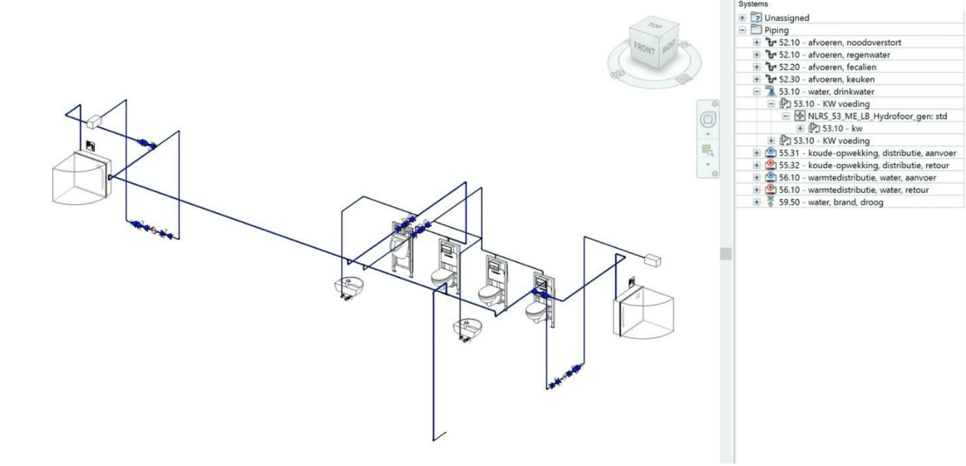 Figure 4.2.2: Cold water pipe system
Exporting to IFC
